Product Description
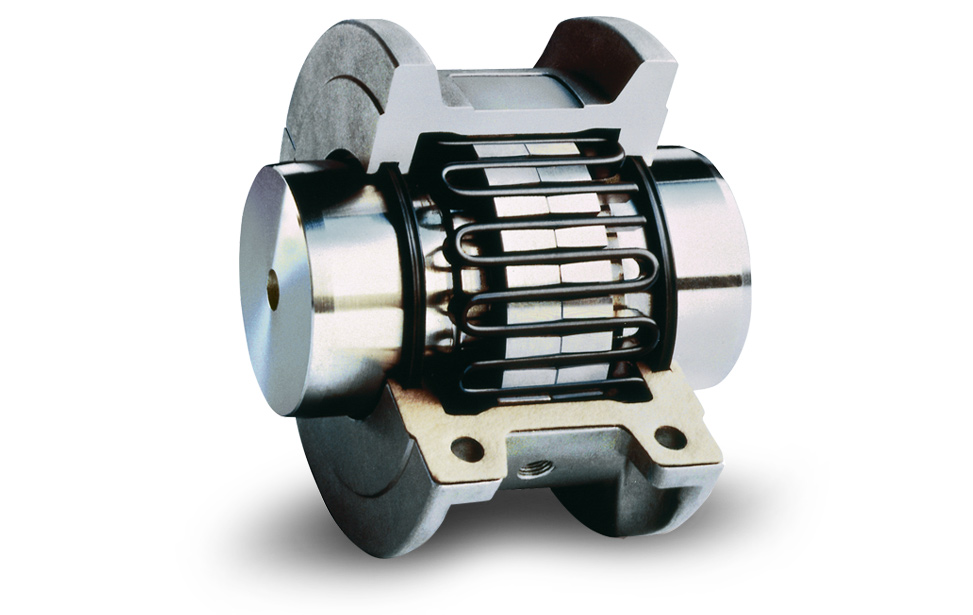
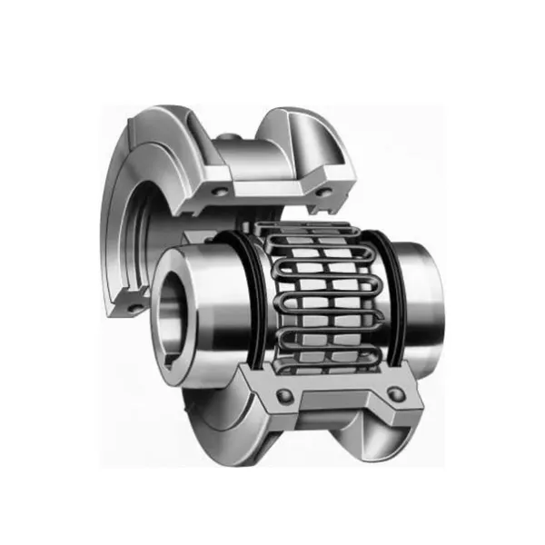
High Quality Rubber Shaft Tyre flexible Coupling For Mechanical Equipment
Features
Material: cast iron GG25, GG20 steel: C45
Parts: 2 couplings and 1 tire body.
Size from F40-F250. and Type: “B”, “F”, “H”.
Working temp: -20~80ºC
Transmission torque:10-20000N.M
Axial misalignment: D*2%
Radial deviation: D*1%
Angular misalignment:3°-6°
Application: tire couplings are usually used in wet, dusty, under attract, vibration, rotating, and complex working conditions. like: diesel pump
Installation: easy on, easy off.
Maintenance: no need for lubricating and durability.
Product Description
| Size | Type | Bush No. | MaxBore | Type F&H | Type H | Serve over Key |
A | C | D | F | M | |||
| mm | Inch | L | E | L | E | |||||||||
| F40 | B | – | 32 | – | – | – | 33 | 22 | M5 | 104 | 82 | – | – | 11 |
| F40 | F | 1008 | 25 | 1″ | 33 | 22 | – | – | – | 104 | 82 | – | – | 11 |
| F40 | H | 1008 | 25 | 1″ | 33 | 22 | – | – | – | 104 | 82 | – | – | 11 |
| F50 | B | – | 38 | – | – | – | 43 | 32 | M5 | 133 | 100 | 79 | – | 12.5 |
| F50 | F | 1210 | 32 | 1 1/4″ | 38 | 25 | – | – | – | 133 | 100 | 79 | – | 12.5 |
| F50 | H | 1210 | 32 | 1 1/4″ | 38 | 25 | – | – | – | 133 | 100 | 79 | – | 12.5 |
| F80 | B | – | 45 | – | – | – | 55 | 33 | M6 | 165 | 125 | 70 | – | 16.5 |
| F80 | F | 1610 | 42 | 1 5/8″ | 42 | 25 | – | – | – | 165 | 125 | 103 | – | 16.5 |
| F60 | H | 1610 | 42 | 1 5/8″ | 42 | 25 | – | – | – | 165 | 125 | 103 | – | 16.6 |
| F70 | B | – | 50 | – | – | – | 47 | 35 | M8 | 187 | 142 | 80 | 60 | 11.5 |
| F70 | F | 2012 | 50 | 2″ | 44 | 32 | – | – | – | 187 | 142 | 80 | 50 | 11.5 |
| F70 | H | 1810 | 42 | 1 5/8″ | 42 | 25 | – | – | – | 187 | 142 | 80 | 50 | 11.5 |
| F80 | B | – | 60 | – | – | – | 55 | 42 | M8 | 211 | 165 | 98 | 54 | 12.5 |
| F80 | F | 2517 | 80 | 2 1/2″ | 58 | 45 | – | – | – | 211 | 165 | 98 | 54 | 12.5 |
| F80 | H | 2012 | 50 | 2″ | 45 | 32 | – | – | – | 211 | 165 | 98 | 54 | 12.5 |
| F90 | H | – | 70 | – | – | – | 63.5 | 49 | M10 | 235 | 188 | 108 | 62 | 13.5 |
| F90 | F | 2517 | 60 | 2 1/2″ | 58.5 | 45 | – | – | – | 235 | 188 | 108 | 62 | 13.5 |
| F90 | H | 2517 | 60 | 2 1/2″ | 58.5 | 45 | – | – | – | 235 | 188 | 108 | 62 | 13.5 |
| F100 | H | – | 80 | – | – | – | 63.5 | 49 | M10 | 235 | 188 | 120 | 62 | 13.5 |
| F100 | F | 3571 | 75 | 3″ | 64.5 | 51 | – | – | – | 235 | 188 | 125 | 62 | 13.5 |
| F100 | H | 2517 | 60 | 2 1/2″ | 58.5 | 45 | – | – | – | 235 | 188 | 113 | 62 | 13.5 |
| F110 | B | – | 90 | – | – | – | 75.5 | 63 | M12 | 279 | 233 | 128 | 62 | 12.5 |
| F110 | F | 3571 | 75 | 3″ | 63.5 | 51 | – | – | – | 279 | 233 | 134 | 62 | 12.5 |
| F110 | H | 3571 | 75 | 3″ | 63.5 | 51 | – | – | – | 279 | 233 | 134 | 62 | 12.5 |
| F120 | B | – | 100 | – | – | – | 84.5 | 70 | M12 | 314 | 264 | 140 | 67 | 14.5 |
| F120 | F | 3525 | 100 | 4″ | 79.5 | 65 | – | – | – | 314 | 264 | 144 | 67 | 14.5 |
| F120 | H | 3571 | 75 | 4″ | 85.5 | 51 | – | – | – | 314 | 264 | 144 | 67 | 14.5 |
| F140 | B | – | 130 | – | – | – | 110.5 | 4 | M16 | 359 | 311 | 178 | 73 | 16 |
| F140 | F | 3525 | 100 | 4″ | 81.5 | 65 | – | – | – | 359 | 311 | 178 | 73 | 16 |
| F140 | H | 3525 | 100 | 4″ | 81.5 | 65 | – | – | – | 359 | 311 | 178 | 73 | 18 |
| F160 | B | – | 140 | – | – | – | 117 | 102 | M20 | 402 | 345 | 187 | 78 | 16 |
| F160 | F | 4030 | 115 | 4 1/2″ | 92 | 77 | – | – | – | 402 | 345 | 197 | 78 | 16 |
| F160 | H | 4030 | 115 | 4 1/2″ | 92 | 77 | – | – | – | 402 | 345 | 197 | 78 | 16 |
| F180 | B | – | 150 | – | – | – | 137 | 114 | M16 | 470 | 394 | 205 | 94 | 23 |
| F180 | F | 4536 | 125 | 5″ | 112 | 89 | – | – | – | 470 | 394 | 205 | 94 | 23 |
| F180 | H | 4535 | 125 | 5″ | 112 | 89 | – | – | – | 470 | 394 | 205 | 94 | 23 |
| F200 | B | – | 150 | – | – | – | 138 | 114 | M20 | 508 | 429 | 205 | 103 | 24 |
| F200 | F | 4535 | 125 | 5″ | 113 | 89 | – | – | – | 508 | 429 | 205 | 103 | 24 |
| F200 | H | 4535 | 125 | 5″ | 113 | 89 | – | – | 508 | 429 | 205 | 103 | 24 | |
| F220 | B | – | 160 | – | – | – | 154.5 | 127 | M20 | 562 | 474 | 223 | 118 | 27.5 |
| F220 | F | 5571 | 125 | 5″ | 129.5 | 102 | – | – | – | 562 | 474 | 223 | 118 | 27.5 |
| F220 | H | 5571 | 125 | 5″ | 129.5 | 102 | – | – | – | 562 | 474 | 223 | 118 | 27.5 |
| F250 | H | – | 190 | – | – | 161.5 | 132 | M20 | 628 | 522 | 254 | 125 | 29.5 | |
Related Products
Company Profile
FAQ
Q: How do you ship to us?
A: It is available by air, sea, or train.
Q: How do I pay the money?
A: T/T and L/C are preferred, with different currencies, including USD, EUR, RMB, etc.
Q: How can I know if the product is suitable for me?
A: >1ST confirm drawing and specification >2nd test sample >3rd start mass production.
Q: Can I come to your company to visit?
A: Yes, you are welcome to visit us at any time.
Can Motor Couplings Compensate for Angular, Parallel, and Axial Misalignments?
Yes, motor couplings are designed to compensate for certain degrees of angular, parallel, and axial misalignments between the motor and driven shafts.
Angular Misalignment: Motor couplings can accommodate angular misalignment, which is the deviation in angle between the motor shaft and the driven shaft. This misalignment occurs when the two shafts are not perfectly collinear. Flexible couplings, such as elastomeric or grid couplings, can provide higher angular misalignment capabilities compared to rigid couplings.
Parallel Misalignment: Parallel misalignment refers to the lateral offset between the motor shaft and the driven shaft. Motor couplings can compensate for this misalignment to a certain extent. Flexible couplings with torsional flexibility, such as elastomeric or grid couplings, are better suited to handle parallel misalignment compared to rigid couplings.
Axial Misalignment: Axial misalignment is the displacement along the axis of the motor and driven shafts. Motor couplings can also accommodate axial misalignment to some degree. The ability to handle axial misalignment varies depending on the coupling type and design.
While motor couplings can compensate for misalignments, it is essential to ensure that the misalignment does not exceed the coupling’s specified limits. Excessive misalignment beyond the coupling’s capabilities can lead to premature wear, increased stress on the coupling and connected equipment, and potential coupling failure.
Choosing the appropriate coupling type and size based on the specific misalignment requirements of the application is crucial for optimal performance, reliability, and longevity of the motor coupling in mechanical power transmission systems.
How to identify signs of wear or failure in a motor coupling?
Identifying signs of wear or failure in a motor coupling is essential for maintaining the efficiency and reliability of a mechanical system. Here are some common indicators to look for:
1. Visual Inspection:
Perform a visual inspection of the motor coupling regularly. Look for any of the following signs:
- Cracks or deformations in the coupling body
- Corrosion or rust on the coupling surface
- Visible signs of misalignment between the shafts
- Excessive wear on the coupling teeth or flanges
2. Abnormal Vibrations:
Unusual vibrations or shaking during motor operation can indicate an issue with the coupling. Excessive play due to wear or misalignment can lead to vibrations that affect the overall system’s performance.
3. Noises:
Listen for any unusual noises, such as clunking, clicking, or rattling sounds during motor operation. These noises could be an indication of loose or damaged coupling components.
4. Misalignment:
Check for shaft misalignment between the motor and driven load. Misalignment can lead to uneven distribution of forces, causing premature wear and failure of the coupling.
5. Increased Friction and Heat:
Feel for any excessive heat generated during motor operation. Increased friction due to misalignment or wear can cause the coupling to overheat.
6. Reduced Performance:
If you notice a decrease in the motor’s performance or efficiency, it could be a sign of coupling wear or failure. Reduced torque transmission or increased power losses may be evident.
7. Shaft Movement:
Check for any axial movement in the motor and driven load shafts. Axial play can indicate a worn or damaged coupling that needs attention.
If you observe any of these signs, it is crucial to address the issue promptly. Regular maintenance, including lubrication and alignment checks, can help prevent coupling failures and extend the coupling’s lifespan. If the coupling shows significant signs of wear or damage, consider replacing it with a new one to ensure optimal performance and avoid costly breakdowns in the future.
“`
Are Grid Couplings Suitable for High Torque and Misalignment Conditions?
Yes, grid couplings are well-suited for high torque and misalignment conditions in industrial applications. They offer several features that make them an excellent choice for such conditions:
- High Torque Capacity: Grid couplings are designed to handle high torque loads, making them suitable for heavy-duty industrial machinery and equipment.
- Misalignment Tolerance: Grid couplings can accommodate both angular and radial misalignments between the connected shafts. This ability to tolerate misalignments is crucial in industrial settings where perfect alignment may not always be possible.
- Vibration Damping: The serrated grid element in grid couplings acts as a vibration damper, absorbing shocks and vibrations that can occur during high-torque operation. This feature helps in reducing noise levels and ensuring smoother machinery performance.
- Shock Load Absorption: Grid couplings are specifically designed to absorb shock loads, which are common in industrial environments. This capability protects the connected equipment from sudden overloads and prevents damage to the machinery.
- Torsional Flexibility: The flexible grid structure of the coupling provides torsional flexibility, allowing it to compensate for torsional vibrations and torque spikes that often occur in high-torque conditions.
Grid couplings are commonly used in applications where high torque is required, such as in pumps, compressors, mixers, and other heavy machinery. Additionally, their ability to handle misalignments makes them suitable for various industrial settings where precise alignment may be challenging.
When properly installed and maintained, grid couplings provide reliable performance in high-torque and misalignment conditions, contributing to smoother machinery operation and extended equipment life.


editor by CX 2023-10-07