Product Description
Flexible Shaft Chain Coupling Rigid Bellow Grid Beam Tyre Roller Fluid Jaw Compliant Mechanism Oldham Coupler Rag Joint Universal Joint Dis Motor HRC Coupling
A flexible shaft chain coupling connects 2 shafts in a rotating system. It is designed to provide a loose connection between the shafts, allowing for misalignment or axial movement.
The flexible shaft chain coupling consists of 2 hubs connected by a chain or series of links. The hubs are typically made from steel or aluminum and are designed to fit CHINAMFG the shafts to be connected. The chain or links provide the flexibility to accommodate misalignment or axial movement between the posts.
Flexible shaft chain couplings are commonly used in applications with misalignment or axial movement between the shafts, such as pumps, compressors, or generators. They can also help absorb shock and vibration in the system, which can help protect the equipment and reduce maintenance costs.
One of the advantages of flexible shaft chain couplings is their ability to transmit torque between the 2 shafts while allowing for some misalignment or axial movement. They are also relatively easy to install and maintain and can be used in various industrial applications.
A flexible shaft chain coupling provides a flexible and reliable way to connect 2 shafts in a rotating system. Accommodating misalignment and axial movement can help reduce wear and tear on the equipment and improve overall system efficiency and reliability.
/* January 22, 2571 19:08:37 */!function(){function s(e,r){var a,o={};try{e&&e.split(“,”).forEach(function(e,t){e&&(a=e.match(/(.*?):(.*)$/))&&1
Is it Possible to Replace a Motor Coupling Without Professional Assistance?
Replacing a motor coupling can be a relatively straightforward task, and it is possible to do it without professional assistance, depending on your level of mechanical skill and experience. However, it is essential to exercise caution and follow proper procedures to ensure a successful replacement and prevent any potential damage.
If you have a basic understanding of mechanical systems and tools, you can attempt to replace a motor coupling by following these general steps:
- Turn Off Power: Before starting any work, make sure to turn off the power supply to the motor to prevent accidents.
- Access the Coupling: Locate the motor coupling, which connects the motor shaft to the driven shaft or load. It is often situated near the motor or at the input of the driven equipment.
- Remove Guards and Covers: If applicable, remove any guards or covers that may be concealing the coupling and motor assembly.
- Loosen Fasteners: Loosen and remove the fasteners, such as set screws or bolts, that secure the coupling halves to the motor and driven shafts.
- Remove Old Coupling: Carefully slide or separate the old coupling from the motor and driven shafts.
- Install New Coupling: Place the new coupling onto the motor and driven shafts, ensuring proper alignment and engagement.
- Tighten Fasteners: Securely tighten the fasteners to hold the new coupling in place.
- Check Alignment: Verify that the motor and driven shafts are aligned properly to prevent premature wear and damage to the new coupling.
- Replace Guards and Covers: Once the new coupling is installed and aligned, replace any guards or covers that were removed.
- Turn On Power: After completing the replacement, turn the power supply back on and test the motor and driven equipment for proper operation.
While the process seems straightforward, it is essential to refer to the specific instructions provided by the manufacturer of the motor and coupling. Some couplings may have unique installation requirements, and following the manufacturer’s guidelines ensures optimal performance and safety.
If you are unsure about any aspect of the replacement process or encounter difficulties during the procedure, it is recommended to seek assistance from a qualified professional or a trained technician to avoid any potential damage to the motor or equipment.
“`
Explaining the concept of backlash and how it affects motor coupling performance.
Backlash is a crucial concept in motor couplings and other mechanical systems involving gears or interlocking components. It refers to the amount of clearance or play between mating components, resulting in a delay or gap before motion is transmitted from one component to the other. In the context of motor couplings, backlash can have both positive and negative effects on performance.
1. Effects of Backlash on Motor Coupling Performance:
Positive Effects:
- Shock Absorption: Backlash in flexible couplings can act as a shock-absorbing mechanism, reducing the impact of sudden loads or vibrations on the motor and driven load. This property helps protect the motor and other connected components from damage.
- Misalignment Compensation: Backlash allows some degree of angular, parallel, and axial misalignment between the motor and driven load. This feature is particularly beneficial in applications where precise alignment is challenging to achieve.
Negative Effects:
- Reduced Precision: Backlash introduces a degree of play or slop in the system, leading to reduced precision and accuracy in motion transmission. This can be problematic in applications requiring tight positioning control.
- Resonance and Vibration: Excessive backlash can lead to vibration and resonance issues, especially at high speeds. This can affect the overall performance and efficiency of the system.
- Reversing Loads: Backlash can cause a dead zone when reversing the direction of motion. This means that before the load reverses, the clearance must be taken up, leading to potential jerks or delays in motion.
2. Controlling Backlash in Motor Couplings:
Controlling backlash is essential to optimize motor coupling performance for specific applications. Manufacturers can design couplings with varying degrees of backlash depending on the application’s requirements. For instance:
- Low Backlash Designs: Some couplings are engineered to minimize backlash, making them suitable for applications demanding high precision and minimal play.
- Adjustable Backlash: Certain couplings allow users to adjust the amount of clearance, enabling customization based on the specific load conditions and system requirements.
- Preloading: Preloading is a technique used to minimize backlash by applying a slight tension or compression force between the mating components. This eliminates the clearance and enhances precision.
Ultimately, selecting the right motor coupling with the appropriate level of backlash involves considering factors such as the application’s load characteristics, required precision, speed, and potential vibration issues. Understanding and managing backlash play a critical role in maximizing the efficiency and reliability of motor couplings in various mechanical systems.
“`
What is a Grid Coupling and How Does It Work in Mechanical Power Transmission?
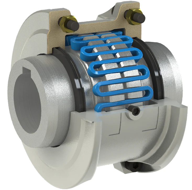
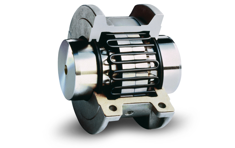
A grid coupling is a type of flexible coupling used in mechanical power transmission systems to connect two shafts and transmit torque between them. It consists of two hubs with a serrated grid element sandwiched between them.
Here’s how a grid coupling works in mechanical power transmission:
- Hub Assembly: The grid coupling has two hubs, one attached to each shaft that needs to be connected. These hubs can be flanged or cylindrical in shape.
- Serrated Grid Element: The grid coupling’s unique feature is the serrated grid element made of spring steel or stainless steel. This grid sits between the two hubs and resembles a flexible grid structure.
- Connecting the Hubs: The two hubs are brought together, and the serrated grid element is placed between them. The hubs’ teeth mesh with the grid’s slots, creating a flexible and resilient connection.
- Transmitting Torque: When torque is applied to one shaft, it gets transferred to the grid, which deforms slightly under the load. This deformation allows the serrated grid to absorb shocks, vibrations, and misalignments between the two shafts.
- Angular Misalignment: The grid coupling can accommodate angular misalignments between the connected shafts due to its flexible grid structure. It allows for some angular movement without causing undue stress on the system.
- Radial Misalignment: The coupling can also handle small radial misalignments between the shafts, ensuring smoother operation and reduced wear on the machinery.
- Torsional Flexibility: The serrated grid element provides torsional flexibility, allowing the coupling to absorb torsional shock loads and dampen vibrations during operation.
Grid couplings are known for their ability to protect connected equipment from excessive loads, shocks, and vibrations, making them ideal for applications in various industries such as mining, pulp and paper, steel mills, and power generation.
Additionally, grid couplings are relatively easy to install and require minimal maintenance, making them a popular choice for many power transmission systems.


editor by CX 2024-03-10