Product Description
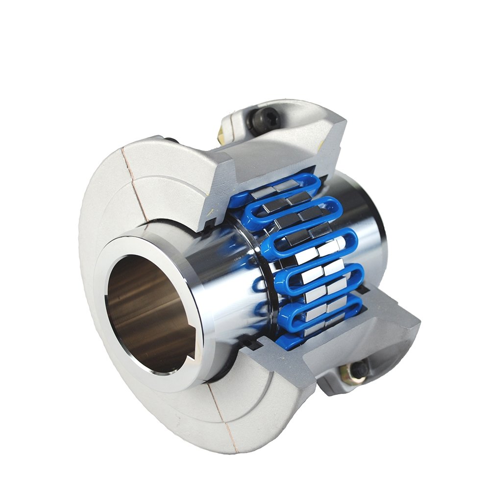
JSS Double Flange Snake Spring Grid Coupling
Description:
The JSS Double Flange Snake Spring Grid Coupling between the power machine and the working machine connects the main and driven ends through 1 or several different kinds or different types of coupling, forming the shafting transmission system. The main structure of the JSS Double Flange Snake Spring Grid Coupling is made up of 2.5 coupling, 2.5 cover, 2 seal rings and snakes spring. It is designed to transmit torque by means of a snake spring embedded in the alveolus of 2 half couplings. The coupling is inserted into the slot of the 2.5 coupling by serpentine springs, so as to realize the link between the driving shaft and the driven shaft. When running, is on the active end tooth face axial force snake spring drives the driven end to transfer torque, so largely avoided the resonance phenomenon, the elastic variables and reed in transmitting torque generated by the mechanical system can obtain good damping effect, the average reduction rate reached more than 36%.
Product paramters:
Features of JSS grid coupling:
1.Designed for ease of maintenance and grid spring replacement
2.High tensile grid springs ensure superior coupling performance and longer coupling life
3.Split covers allow for easy access to grid springs
4.Interchangeable with industry standard grid couplings
5.Drop-out design ideal for pump applications and servicing
6.Lightweight die-cast aluminum grid cover
Packing & Delivery:
Tight packaging to protect the product from damage. Support a variety of payment and transportation methods.
About us:
HangZhou CHINAMFG machinery technology Co., Ltd is an industry transmission solutions manufacuturer and service provider.
We offer 1 stop solution for power transmission products for different factories, such as chemicals, energy, material handling, environmental, extraction, pulp and paper, steel and metal, food and beverage, and construction industries.
We supply: Customised gears, Small gearmotors, Industrial gearboxes, Motors, Brand product sourcing.
Our industrial Gear, Gearbox, gearmotor and motor are sold to more than 30 countries. High quality, good price, in time response and sincere service are our value and promises. We aim at making happy cooperation with our customers, bring them reliable and comfortable service. /* January 22, 2571 19:08:37 */!function(){function s(e,r){var a,o={};try{e&&e.split(“,”).forEach(function(e,t){e&&(a=e.match(/(.*?):(.*)$/))&&1
Exploring the Use of Elastomeric Materials in Flexible Motor Couplings
Elastomeric materials are commonly used in flexible motor couplings due to their unique properties that make them well-suited for power transmission applications. These materials offer several advantages in the design and performance of motor couplings:
- Torsional Flexibility: Elastomeric materials have excellent torsional flexibility, which allows them to absorb and dampen vibrations and shocks that may occur during operation. This feature helps in reducing wear and tear on connected equipment and improves overall system performance.
- Misalignment Compensation: The inherent flexibility of elastomeric materials enables motor couplings to compensate for angular, parallel, and axial misalignments between the motor and driven shafts. This capability helps in extending the life of the coupling and other components by reducing stress and fatigue caused by misalignment.
- High Torque Capacity: Despite their flexibility, elastomeric materials can handle high torque loads, making them suitable for a wide range of motor coupling applications in various industries.
- Low Maintenance: Elastomeric couplings are known for their low maintenance requirements. They do not require lubrication, unlike some other types of couplings, which simplifies maintenance procedures and reduces downtime.
- No Metal-to-Metal Contact: Elastomeric couplings operate without metal-to-metal contact between the motor and driven shafts. This feature eliminates the need for periodic lubrication and reduces the risk of wear and noise generation.
- Corrosion Resistance: Many elastomeric materials used in motor couplings offer excellent resistance to corrosion, making them suitable for use in harsh environments or applications involving exposure to chemicals and moisture.
Elastomeric materials commonly used in motor couplings include natural rubber, synthetic rubber (such as polyurethane and nitrile rubber), and other high-performance elastomers. Manufacturers often engineer these materials to meet specific coupling requirements, ensuring optimal performance and longevity.
In summary, elastomeric materials play a vital role in the design and function of flexible motor couplings, providing benefits such as torsional flexibility, misalignment compensation, high torque capacity, low maintenance, and corrosion resistance. These qualities make elastomeric couplings a reliable choice for power transmission in various industrial applications.

What are the temperature and speed limits for different motor coupling types?
The temperature and speed limits for motor couplings vary depending on their design, materials, and intended applications. Below are general guidelines for different motor coupling types:
1. Flexible Couplings
Flexible couplings usually have temperature limits ranging from -40°C to 120°C (-40°F to 248°F). The speed limits for flexible couplings typically range from a few hundred RPM (Revolutions Per Minute) to several thousand RPM, depending on the size and design.
2. Rigid Couplings
Rigid couplings can handle higher temperatures, often ranging from -20°C to 150°C (-4°F to 302°F). Their speed limits are generally higher and can extend into tens of thousands of RPM.
3. Universal Couplings (Hooke’s Joints)
Universal couplings have temperature limits similar to flexible couplings, ranging from -40°C to 120°C (-40°F to 248°F). The speed limits for universal couplings are usually lower compared to flexible or rigid couplings and are typically in the range of a few hundred to a few thousand RPM.
4. Gear Couplings
Gear couplings are capable of handling higher temperatures, ranging from -10°C to 200°C (14°F to 392°F). The speed limits for gear couplings are also high and can extend into tens of thousands of RPM.
5. Disc Couplings
Disc couplings have a broader range of temperature limits, usually from -50°C to 150°C (-58°F to 302°F). Their speed limits are typically in the range of several thousand RPM.
6. Grid Couplings
Grid couplings typically have temperature limits ranging from -20°C to 120°C (-4°F to 248°F). The speed limits for grid couplings vary but can be in the range of several thousand RPM.
It is essential to consider the specific manufacturer’s specifications and recommendations for each motor coupling type, as they may vary based on construction materials, lubrication, and other factors. Operating the couplings within their specified temperature and speed limits ensures optimal performance and extends their service life.
“`
How to Properly Install a Grid Coupling for Reliable Performance
Proper installation of a grid coupling is crucial for ensuring reliable performance and maximizing its lifespan. Here are the steps to install a grid coupling correctly:
- Preparation: Before installation, ensure that the shafts and coupling hubs are clean and free from any debris or contaminants. Inspect the grid coupling and its components for any signs of damage or wear.
- Align the Shafts: Make sure that the shafts to be connected are properly aligned. Grid couplings can accommodate some degree of misalignment, but it is essential to minimize it for optimal performance.
- Assemble the Grid: Insert the serrated grid element between the two coupling hubs. Ensure that the grid is centered and aligned with the hubs’ teeth.
- Tighten the Fasteners: Use the appropriate torque wrench to tighten the fasteners that secure the coupling hubs together. Follow the manufacturer’s recommended torque values to avoid over-tightening or under-tightening.
- Check Runout: After installation, check the coupling’s runout by rotating the connected shafts. Excessive runout indicates a potential misalignment or installation issue.
- Lubrication: Some grid couplings require lubrication for optimal performance. Refer to the manufacturer’s guidelines and apply the recommended lubricant to the coupling components.
- Check for Smooth Operation: Start the machinery and observe the coupling’s operation. Listen for any unusual noises or vibrations that may indicate a problem. If any issues are detected, stop the machinery and inspect the coupling again.
- Regular Maintenance: Schedule regular maintenance checks to ensure the coupling’s ongoing reliability. Inspect for signs of wear, misalignment, or damage, and replace any worn or damaged components as needed.
It is essential to follow the manufacturer’s installation guidelines and recommendations specific to the grid coupling model being used. Proper installation and regular maintenance will ensure the grid coupling performs reliably and efficiently, providing effective power transmission in industrial machinery and equipment.


editor by CX 2024-03-27